Main Menu (Mobile)- Block
- Overview
-
Support Teams
- Overview
- Anatomy and Histology
- Cryo-Electron Microscopy
- Electron Microscopy
- Flow Cytometry
- Gene Targeting and Transgenics
- High Performance Computing
- Immortalized Cell Line Culture
- Integrative Imaging
- Invertebrate Shared Resource
- Janelia Experimental Technology
- Mass Spectrometry
- Media Prep
- Molecular Genomics
- Primary & iPS Cell Culture
- Project Pipeline Support
- Project Technical Resources
- Quantitative Genomics
- Scientific Computing
- Viral Tools
- Vivarium
- Open Science
- You + Janelia
- About Us
Main Menu - Block
- Overview
- Anatomy and Histology
- Cryo-Electron Microscopy
- Electron Microscopy
- Flow Cytometry
- Gene Targeting and Transgenics
- High Performance Computing
- Immortalized Cell Line Culture
- Integrative Imaging
- Invertebrate Shared Resource
- Janelia Experimental Technology
- Mass Spectrometry
- Media Prep
- Molecular Genomics
- Primary & iPS Cell Culture
- Project Pipeline Support
- Project Technical Resources
- Quantitative Genomics
- Scientific Computing
- Viral Tools
- Vivarium
Combined Infrared and Optogenetic LED Panel
About the Innovation
The IR-Optogenetic LED Panel provides IR (infrared) backlight and optogenetic illumination. The typical application is backlighting for larva or flies, though it can be used in other types of experimental setups. The illuminated area is about 114 x 114 mm (4.5 x 4.5 inches). The optogenetic lighting is broken up into four quadrants to allow targeted optogenetic activation. Four panels can be set up in a square to provide a 228 mm x 228 mm (9 x 9 inches) backlight, resulting in 16 areas with independent on/off control.
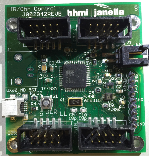
The IR lighting (850nm) is controlled by a single 0-2.5V analog signal (voltage below 0.2V is off). The optogenetic lighting has a single intensity control provided by a 0-2.5V analog signal. Four on/off controls provide the means to turn each optogenetic lighting quadrant on and off. The control signals can be manual (a 5V source is provided to drive external potentiometer/voltage dividers and switches) via a NI-DAQ (or similar digital/analog I/O board) or via the HHMI/Janelia IR/Optogenetic Panel Controller.
A marker signal is available and is typically used to light a separate IR LED in sync with any optogenetic on/off control being on. This allows a camera with a high pass filter to record when optogenetic stimulation is occurring. The marker signal is a logic OR of the 4 on/off signals and the marker input signal. If the marker signal is on when one of the on/off signals is active, the marker LED intensity will increase, which may be useful in certain protocols.
The board should be mounted on a heat sink using 3mm or #4 screws. Plastic washers or screws are required to prevent shorting tracks on the top of the printed circuit board. A non-electrically conductive thermal pad (such as t-Global H48-6G-300-300-0.3) is necessary between the board and the heat sink. The heat sink requirements vary depending on the LED intensities used and the duty cycle. A piece of aluminum plate may be sufficient in low light; higher intensities may require a finned heat sink or cold plate. Adapter plates can be made to attach the panel to a standard optical breadboard or cold plate.
A 6.3mm (1/4") hole is placed in the center of the lighted area to allow for plumbing or wiring to extend up through the board.
Opportunity:
Free to make for Non-Profit Research by emailing innovation@janelia.hhmi.org (they are too large to post).
Designs are also available for commercial licenses.
For inquiries, please reference:
Janelia 2016-001

